Designing Snap-Fit Joints for 3D Printed Enclosures
Designing reliable snap-fit joints on FDM parts requires calculating beam deflections, utilizing generous fillets to distribute strain, and aligning layer lines parallel to the bending force.
Fastening without Hardware
Snap-fit joints are an elegant, cost-effective way to assemble plastic enclosures and parts. They eliminate the need for screws, metal inserts, or glues, allowing components to snap together securely using the natural elasticity of the polymer.
However, designing snap-fits for 3D printed parts is challenging. Because FDM prints are anisotropic and have layer lines, a poorly designed snap-fit will shear or snap off during assembly.
Never design snap-fit joint beams to print vertically along the Z-axis, as the flexing forces will cause the layers to cleave. Always design a generous radius at the root of the cantilever beam to distribute stress.
1. The Cantilever Snap-Fit Model
The most common snap-fit is the cantilever beam. It consists of a projecting arm with a hook at the end, which deflects as it slides over a retaining lip and snaps into place.
`
Cantilever Snap-fit Beam (Conceptual Profile)
_
| \_ <- Hook
| Arm |
=====+===========+===== <- Root (Fillet here!)
| Base
`
To prevent the arm from snapping during deflection, you must calculate the maximum strain.
- Taper the Beam: Tapering the cantilever arm (making it thicker at the base and thinner at the tip) distributes stress uniformly along the length of the beam, allowing for greater deflection without failure.
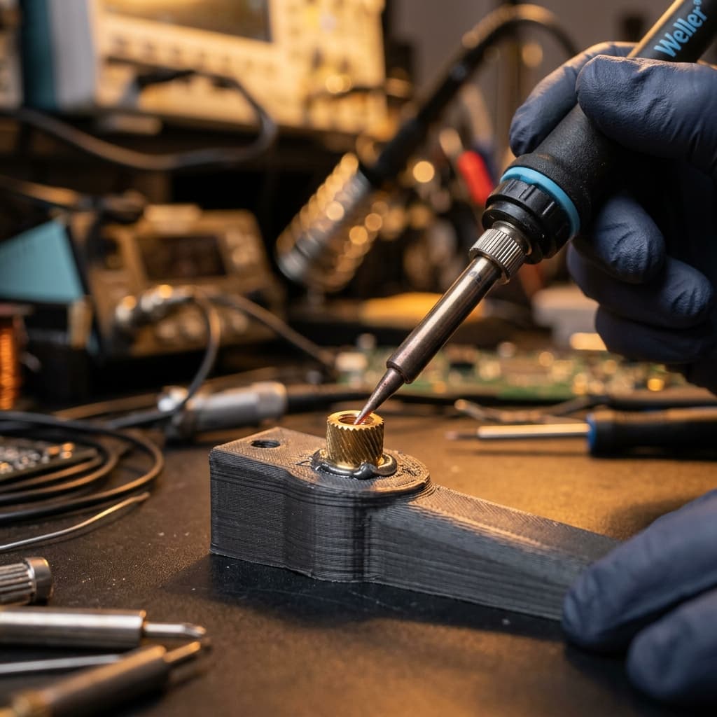
- Fillet the Root: The intersection where the arm meets the base (the root) is a high-stress area. Always design a generous fillet (at least 0.5 to 1 times the beam thickness) to prevent stress concentration.
2. Print Orientation is Everything
Because layer adhesion is the weakest link in FDM printing, the direction the beam bends must run parallel to the layers, not perpendicular.
- Horizontal Printing: If the cantilever beam prints horizontally (flat on the build plate), the tensile bending stress acts along the continuous plastic strands. The joint will be highly flexible and durable.
- Avoid Vertical Printing: If the beam stands vertically, the bending force acts to pull the layers apart (interlaminar tension). The snap-fit will break along a layer boundary at the first assembly attempt.
3. Material Selection
For snap-fit joints, avoid brittle materials like standard PLA. Instead, choose materials with high yield strength and elasticity:
- PETG: Excellent flexibility and chemical resistance.
- Nylon (PA): Outstanding toughness and wear resistance, making it the gold standard for snap-fits.
Secure Enclosure Design Reviews
At NovaLab 3D, we evaluate the snap-fit geometries of your custom housing designs before production to ensure they won't fail during assembly. Upload your CAD designs to get started.
Frequently Asked Questions
Keagan Walker
Founder & Lead Designer
NovaLab 3D is a boutique engineering and additive manufacturing studio based in Pickering, North Yorkshire. We provide B2B clients and product developers with direct access to lead engineering consulting, fast 48-hour turnarounds, and custom FDM production runs.