A Guide to FDM Tolerances for Product Designers
Achieving functional assemblies requires planning for FDM print clearances. Budgeting ±0.2mm tolerances for standard printers guarantees parts fit together perfectly.
Real-World Tolerances
One of the most common challenges in product development is transitioning from a perfect digital CAD model to a physical assembly. In CAD, a 10.0mm pin fits perfectly into a 10.0mm hole. In the physical world, material shrinkage, nozzle diameter, and machine movements mean they will seize or fail to assemble.
Understanding FDM (Fused Deposition Modelling) printing tolerances is essential for ensuring functional assemblies, slide fits, and screw threads work on the first print.
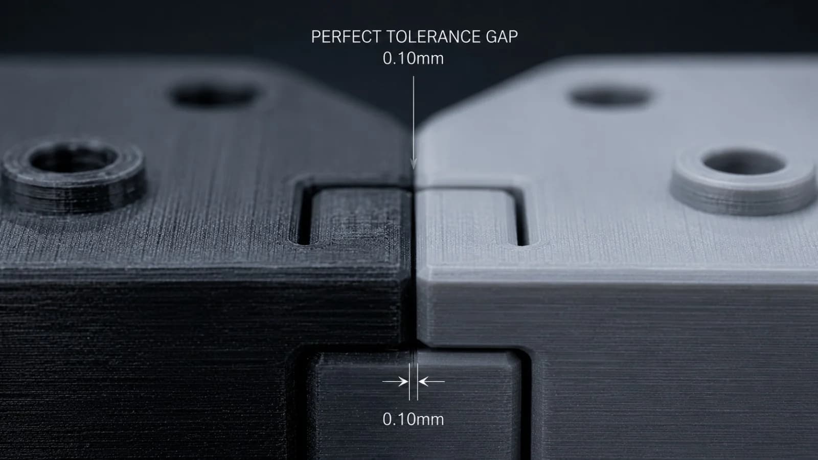
Standard FDM accuracy is ±0.2mm. Interlocking fits require clearances ranging from 0.15mm (tight press-fit) to 0.3mm (smooth slide-fit) to account for machine movements.
1. The Standard FDM Tolerance Envelope
For most professional FDM printers, the baseline dimensional accuracy is ±0.2mm. This means a part designed to be 50.0mm wide will typically measure between 49.8mm and 50.2mm when printed.
If you are designing interlocking components or assemblies, you must design a physical gap (clearance) between them to compensate for this variance.
- Tight Press-Fit: 0.1mm to 0.15mm clearance. Requires light pressure or tapping to assemble.
- Standard Slide-Fit / Friction Fit: 0.2mm to 0.3mm clearance. Allows parts to slide smoothly against each other but remain aligned.
- Loose Clearance Fit: 0.4mm+ clearance. For hinge pins, linkages, or components that need to rotate freely.
2. Inner Diameters (Holes) vs. Outer Diameters (Pins)
A critical rule in 3D printing is that vertical holes always print slightly smaller than designed. This is because the extruded plastic path is pulled inward along the circle's radius as the nozzle deposits the perimeter lines.
- The Rule of Thumb: If you need a bolt to slide cleanly through a 5.0mm clearance hole, design the CAD diameter to be 5.2mm to 5.4mm.
- Alternatively, you can print the hole slightly undersized (e.g. 4.8mm) and drill it out to a perfect 5.0mm diameter after printing for high-precision fits.
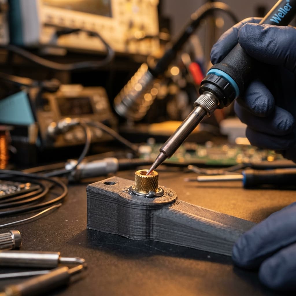
3. Designing Screw Threads for 3D Printing
We regularly print custom threaded parts. For the best results:
- Use Metric M-Profile Threads: Keep threads coarse. Fine threads (pitch under 1.0mm) will merge and fail to separate.
- Apply Thread Clearance: For custom screw assemblies, offset the face of the internal thread or external thread by 0.15mm to 0.2mm in CAD.
- Horizontal Orientation: Vertical threads print beautifully. Threads printed horizontally (resting on their sides) will suffer from stair-stepping and support-material scarring, making them unusable.
Direct Design Reviews
At NovaLab 3D, we don't just hit 'print' on your files. We evaluate tolerances, overhangs, and print orientations. If we notice an assembly hole or slide clearance that looks too tight, we will contact you to discuss adjustments before starting production.
Whether you are based in Leeds, Pickering, or anywhere else in the UK, we are here to support your engineering journey.
Frequently Asked Questions
Keagan Walker
Founder & Lead Designer
NovaLab 3D is a boutique engineering and additive manufacturing studio based in Pickering, North Yorkshire. We provide B2B clients and product developers with direct access to lead engineering consulting, fast 48-hour turnarounds, and custom FDM production runs.